


Chọn nhãn hiệu
Chọn danh mục
Hỗ trợ trực tuyến
- P.Quảng Bá Kỹ Thuật


Điện thoai:0902720814
- P.Quảng Bá Kỹ Thuật
Điện thoai:0907450506
- P.Quảng Bá Kỹ Thuật
Điện thoai:0902601875
- P.Quảng Bá Kỹ Thuật
Điện thoai:0979737351
- P.Quảng Bá Kỹ Thuật
Điện thoai:0902800728
- P.Quảng Bá Kỹ Thuật
Điện thoai:0766226161
Góc kỹ thuật
Liên hệ

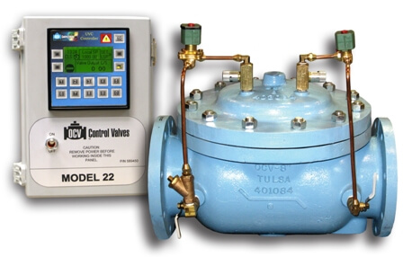
ELECTRONIC CONTROL VALVE - SERIES 22
- Danh mục: VAN ĐIỀU KHIỂN
- Nhãn hiệu: OCV-MỸ
- Giá:
- Model: SERIES 22
- Size:
- Số lượng:
- Mua ngay Thêm vào giỏ
 DOWNLOAD CATALOG
Van Điều khiển điện tử Series 22 đã phát triển và phổ biến các hệ thống SCADA, CAN, Intranet và Cellular đã tăng yêu cầu đối với các van điều khiển điện tử có giao diện với các hệ thống này. Van điều khiển kỹ thuật số OCV Series 22 được thiết kế riêng cho nhiệm vụ này. Mặc dù vẫn giữ được những ưu điểm của sự đơn giản và vận hành áp suất đường dây, các van này mang đến sự dễ vận hành và mức độ linh hoạt chưa đạt được trước đây. * Lưu ý: Để làm rõ, về thuật ngữ điện tử, hãy tham khảo Thuật ngữ điện tử OCV
Series 22 Electronic Control
The development and proliferation of SCADA, CAN, Intranet, and Cellular systems has increased the requirement for electronically controlled valves that interface with these systems. The OCV Series 22 Digital Control Valves were specifically designed for this task. While retaining the advantages of simplicity and line pressure operation, these valves offer an ease of operation and degrees of flexibility not previously achieved.
*Note: For clarification, of electronic terminology refer to the OCV Electronic Glossary
| Model | Model Sheet | Model Sheet (metric) | Specifications | Animation | Operations Manual |
|---|---|---|---|---|---|
| Electronic Glossary |  |
|
|||
| Model 22VMU Flow Measurement and Flow Control System | |
|
|||
| Model 22X Electronic Position Control Valve | |
|
|||
| Model 22F Electronic Flow Control | |
|
|||
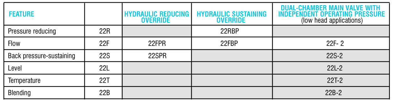
| Model 22R Electronic Pressure Reducing | |
|
|||
| Model 22S Electronic Pressure Sustaining | |
|
|||
| ValveMeter Lite Flow Measurement System | |
Valve Features
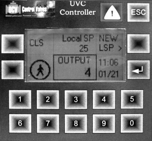
THE CONTROLS
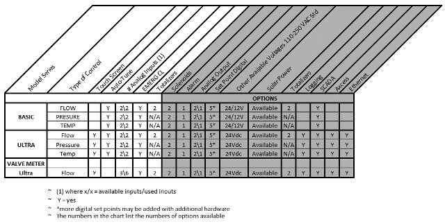
The OCV “Universal Valve Controller” (UVC) is a series that has been built and designed to provide numerous control functions for the OCV control valve. In addition, the UVC can be customized for specific user requirements.
FEATURES OF UVC CONTROLLERS
- Field upgradeable-Should system require
- Process Variable Input
- Analog (0-10V, 4-20mA)
- Digital (pulse)
- Remote Access / Communication (SCADA)
- 4-20mA for Remote Set Point
- RS232/RS485 Communication Port
- Internal Real Time Clock
- Time, Day of Week
- Enclosure: NEMA 4X (IP66)
- Electronic Controllers are UL Listed
- Operational Power
- 110-250 VAC, 50/60 Hz (less than 30 Watts
- Battery backup and DC Models are available-consult factory
- Power Saving Options
- Adjustable Display Activities
- Adjustable Solenoid Activation Cycle Time (where applicable)
In addition to the above features, two upgrade models are available. They include all of the above options, plus what is listed below.
UVC BASIC
*Display may vary
Features of the UVC Basic:
- 128X64 Graphic Monochrome Display
- 15 Keys for entry and scrolling
Special Optional Features:
- Analog Output (4-20mA)
- Additional Discrete Inputs and Outputs
- SMS (text) Messaging by GSM Modem
UVC Basic Typical Applications:
- Pressure Control
- Level/Altitude Control
- Flow Control with External Flow Meter
- Flow Metering
- Consult factory for others
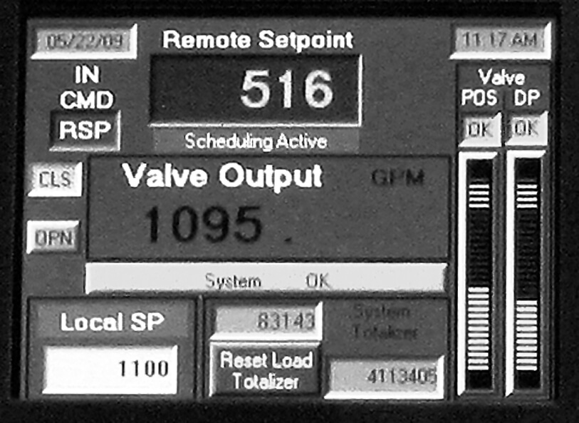
UVC ULTRA
*Display may vary
Specific Features of the UVC Ultra:
- 320X240 Color Graphic Display
- 5 Keys and Virtual Keyboards
- Touch Screen
- Logging Capabilities
Special Optional Features:
- Analog Output (4-20mA)
- MODBUS Protocol Support
- Additional Discrete Inputs and Outputs
- SMS (text) Messaging by GSM Model
- Ethernet Communications
- Email generation upon valve errors; sends to 1-5 email addresses
UVC Ultra Typical Applications:
- Pressure Control
- Level/Altitude Control
- Flow Control without External Flow Meter
- Flow Metering
- Consult factory for others
Valve Operation
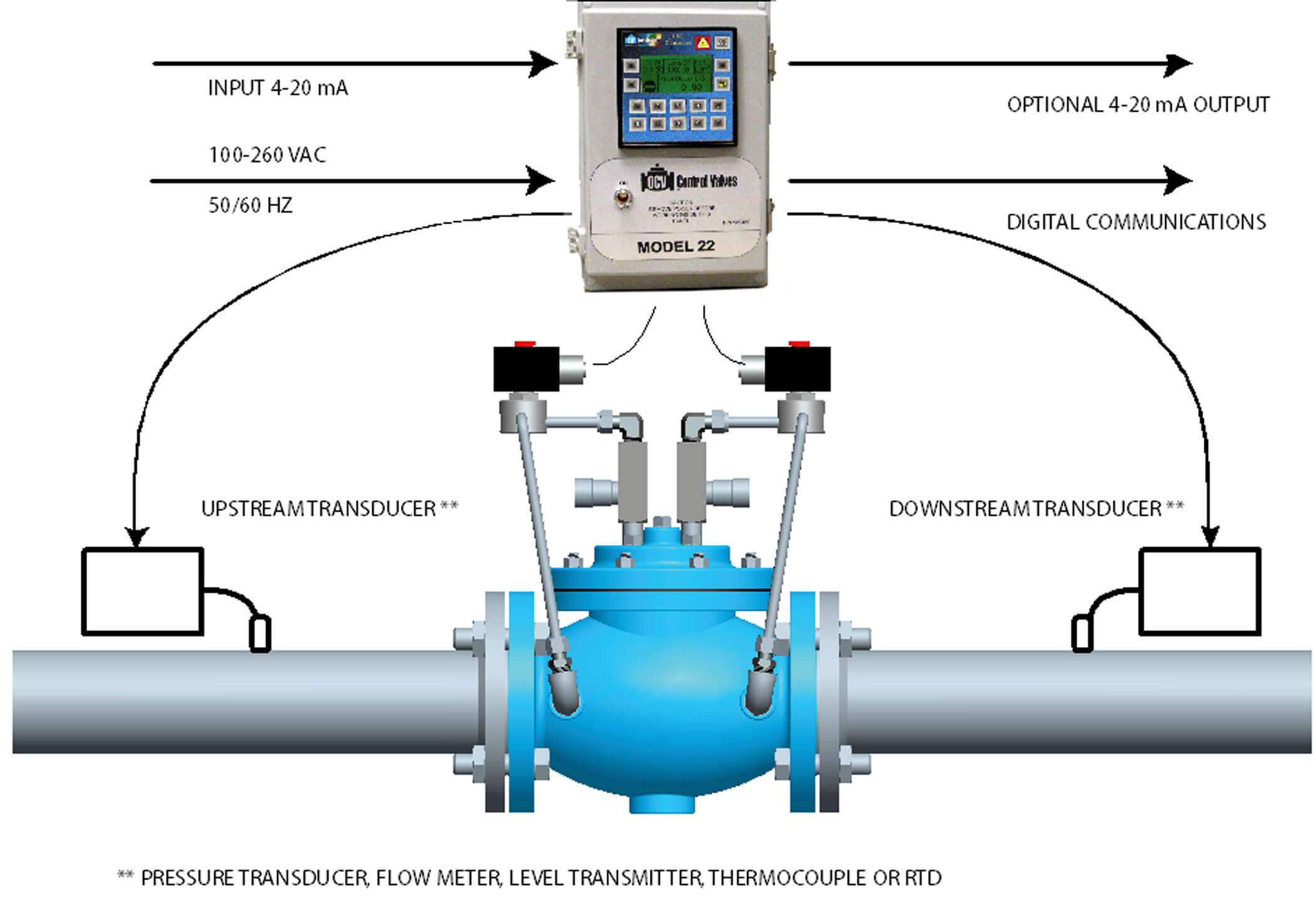
OPERATING PRINCIPLES OF THE SERIES 22 CONTROL VALVE
The system consists of:
- Universal Controller (UVC)
- Process Transducer(s)
- Model 115-3, hydraulically operated, dual solenoid controlled valve
- Valve Position Transmitter-required on some valves, optional on others
UVC Valve Controller
The UVC Controller is the electronic brains of the system. It is a highly sophisticated electronic module whose purpose is to control a process variable (flow, pressure, etc). The UVC receives input, compares it to the desired control setting and then sends electrical power to the valve solenoids until the desired setting is reached.
Model 115-3 Control Valve
The 115-3 valve is the dual solenoid, diaphragm actuated control valve for the series 22 electronic control valve. It is positioned by its two solenoid pilots (2) and (3). With pilot (2) closed and pilot (3) open, the diaphragm chamber of the main valve (1) in vented to downstream and the valve moves further open at an adjustable rate. Conversely, with pilot (2) open and pilot (3) closed, inlet pressure is applied to the main valve diaphragm chamber, moving the valve further closed at an adjustable rate. Finally, with both pilots closed, the diaphragm chamber is “hydraulically locked” (no flow on or off the chamber) and the valve holds its position. The 115-3 valve can be ordered with normally open, or normally closed pilots. In the event of failure, the valve will close, open or hold its last position depending on which failure position is specified.
UVC Operation with Valve
The UVC receives a signal (PV) from the process transducer and compares it to the programmed set point. If the PV is outside of the small dead band around the set point, the controller begins pulsing the appropriate solenoid pilot open and closed on a time proportional basis, with the amount of open time directly proportional to the deviation from the set point. Hydraulic locking occurs when the process variable is within the dead band around the set point. The pulsing action enables the set point to be maintained within close limits, with a minimum of overshoot or “hunting” when process conditions change. The locking action gives the valve extreme stability, even at highly throttled (low flow) positions. The UVC can be configured to either close, open or hold last position in the event input signal failure.
Valve Position Transmitter
The valve position transmitter (optional) uses movement of the valve stem to provide a 4-20mA analog signal proportional to the valve position. The signal increases as the valve opens. Mounted to the center port of the valve bonnet, a rod is threaded into the main valve stem. The valve position transmitter may be installed on virtually any OCV Control Valve without disassembly of the valve itself.
Process Transducer
A Process Transducer is a device that converts pressure flow, temperature, or level to an electrical measurement (e.g., Volts, Milliamps, frequency or pulses).
Sizing
SIZING OF SERIES 22 ELECTRONIC CONTROL
For the most comprehensive procedure in sizing Electronic Control Valves, it is best to use our ValveMaster software. In it’s absence, the following procedure will generally suffice.
- Decide whether a globe or angle valve will best fit your installation. Keep in mind that it is always best to install any control valve “bonnet up,” particularly in sizes 8” and larger.
- Begin with a line sized valve. Calculate the pressure drop from the formula,
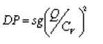
where:
DP = pressure drop, psi
sg = specific gravity of line fluid (water = 1.0)
Q = Maximum anticipated flow, gpm
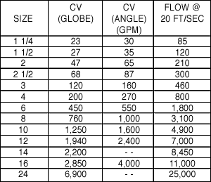
Cv = Valve coefficient from Table 2. - The pressure drop calculated is that for a wide-open valve. However, these valve are modulating and actual pressure drop seen could be higher, dependent upon the valve function (i.e. pressure reducing). Because the calculated pressure drop is calculated at maximum anticipated flow, it is useful to ensure that system capacity is not exceeded.
- Check to see that the flow velocity does not exceed 20 ft/sec. If it does, or if the pressure drop is excessive, consider using the next size larger valve.
FLOW CHARACTERISTICS
Valve Selection Guide
VALVE MODEL SELECTION CHART
CONTROLLER SELECTION GUIDE
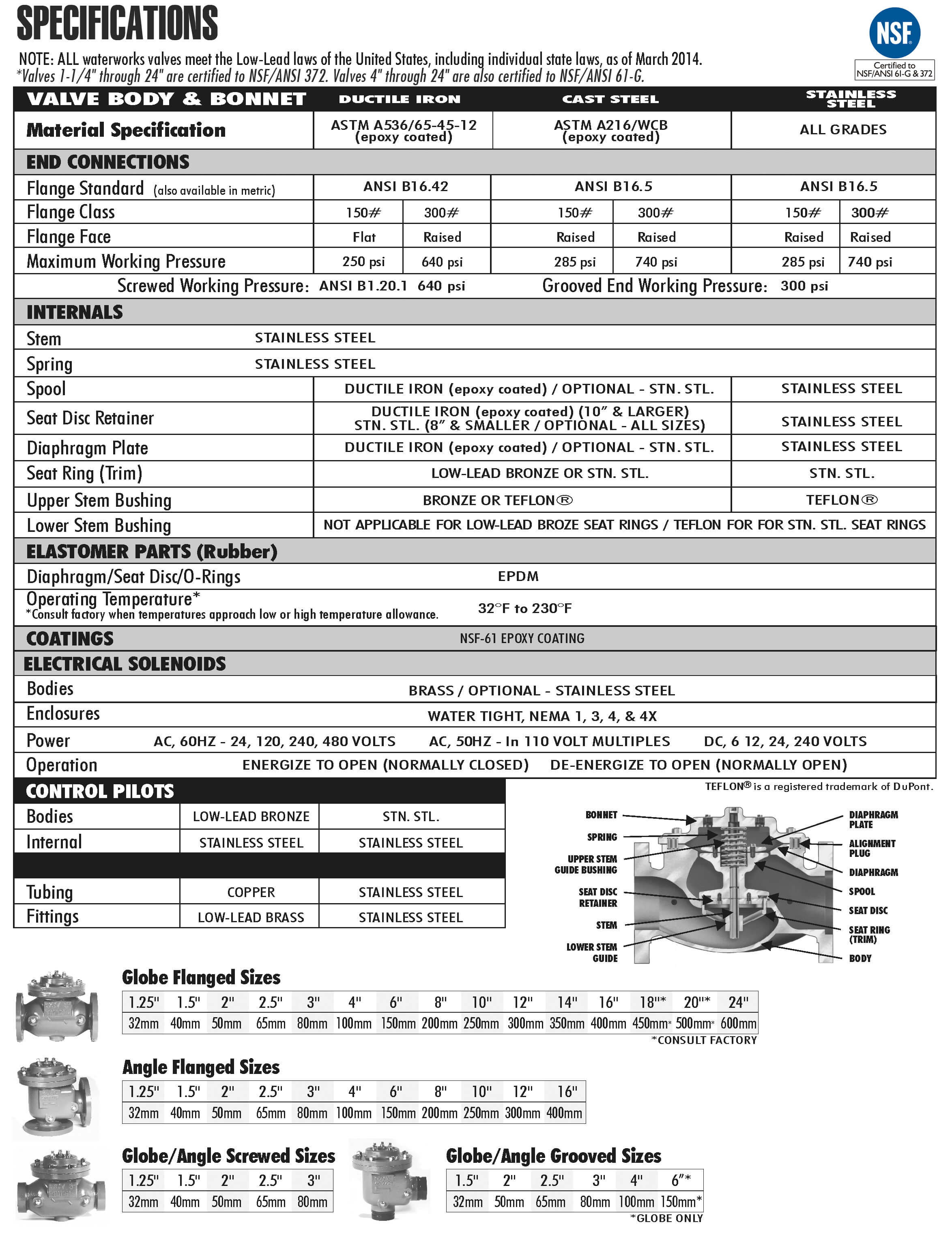
Material Specifications
Material Specifications
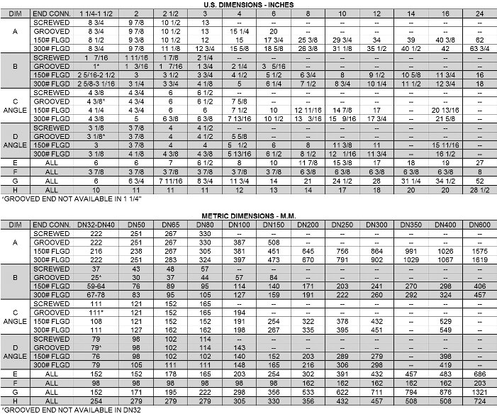
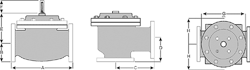
Dimensions
For maximum efficiency, the OCV control valve should be mounted in a piping system so that the valve bonnet (cover) is in the top position. Other positions are acceptable but may not allow the valve to function to its fullest and safest potential. In particular, please consult the factory before installing 8″ and larger valves, or any valves with a limit switch, in positions other than described. Space should be taken into consideration when mounting valves and their pilot systems.
A routine inspection & maintenance program should be established and conducted yearly by a qualified technician. Consult our factory @ 1-888-628-8258 for parts and service.
HOW TO ORDER YOUR VALVE:
When Ordering please provide:
Series Number – Valve size – Globe or Angle – Pressure Class – Screwed, Flanged, Grooved – Trim Material – Adjustment Range – Pilot Options – Special needs / or installation requirements.


Mst: 0314405007
Tel: +842835352125
Email: info@pm-e.vn
Website: www.pm-e.vn
